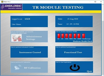

Digilogic Transmitter & Receiver (TR) Module ATE Test platform is a COTS equipment-based test system designed to address various types of TR Module performance & functional testing. This system is capable of generating and analyzing the required signals in the specified band for the TR module operation.
This test system can be capable of testing the TR modules in different frequency bands as per the customer’s requirement. By adding switching subsystem support to this platform, we can have a scalable architecture to test multiple TR Modules (TRM) or Plank (Series of TRMs) at a time or one after the other.
SYSTEM CONFIGURATION:
- Industrial PC/ Server Workstation with LabVIEW customized application software for TR Module Testing.
- Digital / Analog Controls for TR Module Communication & Control.
- Rack Mountable hardware of Signal Generator, Signal Analyzer, Oscilloscope, Vector Network Analyzer, Noise Figure Analyzer, Power meter, Digital Multimeter & Power Supplies.
- RF Switch Matrix for TR Module automatic switching (For single TRM, Multiple TRM for Plank Module).
FEATURES:
- Signal
- Generator
- Signal Analyzer
- Vector Network Analyzer
- Noise Figure Analyzer
- Power Meter
- Oscilloscope
- DMM
- Programmable Power Supplies
- RF Switch Matrix
DIGITAL I/O’s USED:
- TTL/LVTTL/LVDS interfaces
- Industrial DIO
COMMUNICATION INTERFACE:
- SPI
- RS232/RS422
RF COMPONENTS REQUIRED:
- Attenuators, Circulators, detectors & couplers
- Splitters/Power dividers
SYSTEM SELF-TEST:
The TR Module ATE platform performs the functional tests on Single Channel TRM, Multi-Channel TRM & Plank Unit TRM connected to the ATE using the appropriate Interface Test Adapter/Cable Harness using the RF Switch Matrix. The TRM ATE test software will load the test sequences as per the user-defined list and will execute the commands for each test case accordingly. Results of parameters measured at each test sequence will be acquired, recorded and reported as per user-defined test report format on completion of the test sequence.
MEASUREMENT PARAMETERS:
TR Module Level:
- S-Parameters Calibration
Transmitter Test Parameters:
- Output Power Level
- Pulse Parameters (Rise Time, Fall Time, Droop)
- Pulse to Pulse Phase & Amplitude Stability
- Gain Measurement
- Spectral Analysis – Spurious &Harmonics Measurement
- Tx/Rx Switching Time Measurement (ON/OFF Control)
- Power Supply Voltage & Current Monitoring
Receiver Test Parameters:
- Receiver Gain Measurement
- Tx/Rx Switch Isolation, Switching Time Measurement
- Phase shifter & Attenuator performance (If Applicable)
- Noise Figure Measurement
- 1dB Compression Point Measurement
- VSWR/Return loss measurement
- LNA Recovery Time Measurement
- Power Supply Voltage & Current Monitoring
INTERACTIVE USER INTERFACE:


