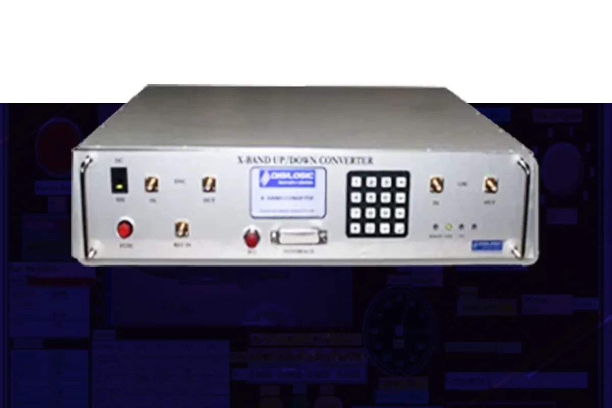
Digilogic’s RF UP/Down Converter for VST has been designed with latest cutting edge technology which is compatible with National Instruments hardwares / products. To extend the frequency range of operation of Vector Signal Transceiver (VST), we can use this up/down converter with VST. It will up-convert the IF signal of VST either to X or Ku band and down-convert X or Ku band input signal to IF frequency level acceptable for Vector Signal Transceiver.
We can also share 10 MHz clock between this up/down converter and VST. We have two bandwidth options available one with 200 MHz and another with 1 GHz. It also comes with a programmable attenuator on the output path providing upto 100 dB of attenuation in 0.5 dB steps.
|
Sl. No.
|
Description
|
Specification
|
|---|---|---|
|
A |
Downconverter Specifications |
|
|
01 |
1 Input Frequency (RF IN) |
X - Band (8 - 12 GHz)/Ku band (12-18 GHz) |
|
2 |
Output Frequency (IF OUT) |
2.5 – 3.5GHz Range |
|
3 |
Frequency Tuning Step Size |
1 KHz |
|
4 |
Bandwidth |
1 GHz/200 MHz |
|
5 |
No. of Channels |
1 |
|
6 |
Input Power |
-50 dBm to 0 dBm |
|
7 |
Max Input Power w/o Damage |
+30 dBm |
|
8 |
Input SFDR |
50dB |
|
9 |
Amplitude Flatness |
± 3 dB (Within 1GHz Bandwidth) |
|
10 |
Spurious |
Better than -60 dBc |
|
11 |
Residual LO Power |
< -60 dBm |
|
12 |
VSWR |
Better than 1.5:1 |
|
13 |
Noise Figure |
10 dB |
|
14 |
Impedance |
50 Ohm |
|
15 |
Gain factor |
0 dB |
|
16 |
Connectivity |
RF IN & IF OUT: SMA (female) |
|
B |
Upconverter Specifications |
|
|
17 |
Input Frequency (IF IN) |
2.5 – 3.5 GHz Range |
|
18 |
Output Frequency (RF OUT) |
X - Band (8 - 12 GHz)/Ku Band (12-18 GHz) |
|
19 |
Frequency Tuning Step Size |
1 KHz |
|
20 |
Bandwidth |
1 GHz/200 MHz |
|
21 |
No. of channels |
1 |
|
22 |
Output Power Control Range |
100 dB (Attenuation) |
|
23 |
Resolution of Power Control |
0.5 dB steps |
|
24 |
Attenuation update rate |
2 MHz |
|
25 |
Input Power to Upconverter |
-50 to 0 dBm |
|
26 |
Amplitude Flatness |
± 3 dB (Within 1GHz Bandwidth) |
|
27 |
Gain factor |
0 dB |
|
28 |
Output Frequency Accuracy |
± 0.5 ppm |
|
29 |
Spurious in 1 GHz BW |
Better than 50dBc |
|
30 |
Residual LO Power |
< -60 dBm |
|
31 |
VSWR |
Better than 1.5:1 |
|
32 |
Noise Figure |
15 dB |
|
33 |
Impedance |
50 Ohm |
|
34 |
Connectivity |
IF IN & RF OUT: SMA (female) |
|
C |
General Specifications |
|
|
35 |
Type of Waveforms |
CW, RF Pulses, Modulated RF Pulses, CW + PRT Train |
|
36 |
Min Pulse Width |
50 ns |
|
37 |
Min PRT |
500 ns |
|
38 |
Max Signal Bandwidth |
1 GHz/200 MHz |
|
39 |
Pulse ON to OFF Isolation |
80 dB |
|
40 |
Total Loop Delay |
~ 1 us |
|
41 |
LO |
Common for Up/Down Converters |
|
42 |
External Reference In Frequency |
10 MHz, 1.65VPP into 50 Ohms, Sine wave |
|
43 |
Image Rejection |
-75 dBc, Typical |
|
44 |
Phase Noise |
-99 dBc, Typical at 20 kHz offset (single sidebanded) |
|
45 |
Interface 1 |
TTL Digital Control for tuning frequency & amplitude |
|
46 |
Interface 2 |
BNC Connector to accept PRF input |
|
47 |
Power Supply |
AC 230 V, 50 Hz |
|
48 |
Operating Temperature |
0° – 50° C |
|
49 |
Size |
2U, 19” Rack mountable, 400mm Depth |
|
50 |
Weight |
Appx 15 kgs |
|
51 |
Remote Control Interface |
USB, LAN |
Explore product details, specifications and features engineered for your needs.
Digilogic Systems Limited (formerly known as Digilogic Systems Private Limited) headquartered in Hyderabad, is an AS9100D and ISO 9001:2015 certified company offering test solutions and simulation systems for defence and aerospace sectors.
#102, 1st floor, DSL Abacus Tech Park, beside DSL Virtue Mall,
Uppal, Hyderabad, Telangana-500039.
#216, 3rd Floor, Zareen Heights, Varthur Road, Nagavarapalya,
C. V. Raman Nagar, Bengaluru, Karnataka – 560093.
© 2026 Digilogic Systems Limited